DESCRIPTION
PRODUCT DESCRIPTION
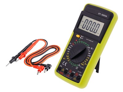
Voltage meter is suitable for home use and for professionals in the electrical industry.
Voltage meter can be used to measure DC and AC voltage, DC flow rate and resistance. The readable display makes it easy to read the measurement results.
Specification:
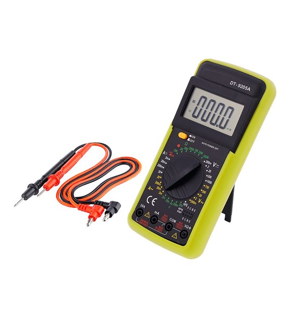
19 switch ranges
COM Socket: measuring socket, black "-" lead
input Socket: VΩmA, red wire "+", measurement V, A (except 10A range), R.
10A Socket: measuring socket for 10A range, red wire "+"
transistor measurement socket
overload protection
automatic shutdown
low battery signaling
audible alarm
Directions for use:
A DC current measurement:
Set the range switch to the appropriate DCA range. Connect the red test lead to the VΩmA socket (up to 200mA, for currents over 200mA to 10A, the 10A socket is appropriate) and the black one to the COM socket.
Connect the test leads in series with the measured circuit.
Read the value on the display (shown polarity of the red test lead).
Voltage measurement V DC and V AC:
Set the range switch to the appropriate DCV and ACV range (if we do not know the value of the measured voltage - select the largest range). Connect the red test lead to the VΩmA socket and the black one to the COM socket.
Connect the parallel test leads to the measured circuit.
Read the value on the display (shown polarity of the red test lead).
Transistor test:
Set the meter's range switch to the hFE position. Insert the tips of the transistor appropriately (ECBE) (PNP / NPN) into the test socket.
Read the approximate hFE value (Ib = 10µA / Vce = 2.8V).
Before measuring, disconnect the test leads from the circuits being measured.
Diode test:
Connect the black test lead to the COM jack and the red test lead to VΩmA.
Set the range selector to the position and connect the red test lead to the anode and the black test lead to the cathode of the diode being measured. The meter will show the approximate diode forward voltage. "1" will be displayed for reversed cables.
Resistance Measurement:
Connect the black test lead to the COM jack and the red test lead to VΩmA.
Set the meter range switch to the Ω position and connect the test leads to the resistor under test. Read the value on the display.